Brush Cutting Machine (Patent No: 132894)
Inventor: Donnelly, Roger Location: Clyde Comments: N/A Description: Claim.
1. The combination with a suitable supporting means, of knives passing from the front of such means to the sides thereof and being supported by the same, and means for adjusting the knives, as and for the purpose specified.
2. The combination with a suitable supporting means, of knives located to the sides of the aforesaid means and converging to the front of the same, means for adjusting the knives, and means supporting the knives from the aforesaid supporting means, as and for the purpose specified.
3. The combination with a suitable supporting means, of a set of knives located at the sides of the aforesaid means and converging forwardly to the front of the same, shields adjoining the knives, means for adjusting the knives, and means for raising or lowering the same in respect to the supporting' means, as and for the purpose specified.
4. The combination with a suitable supporting means, of knives located to the sides of the supporting means and converging forwardly to the front of the same, plates secured to the knives, shields adjoining the knives and secured to the plates, means for adjusting the knives, and means securing the knives adjustably to the supporting means aforesaid, as and for the purpose specified.
5. The combination with a suitable supporting means, of knives located to the sides of the supporting means and converging to the front of the same, said knives being narrow at the front and wide at the rear, p1ates secured to the knives and passing beyond the inner edges of the same, shields adjoining the knives and permanently secured to the plates, cross rods passing between the plates and swingably secured to the same, adjusting screws carried by the rods and bearing normally on the plates, and means supporting the knives adjustably from the supporting means and ill respect to the same, as and for the purpose specified.
6. The combination with a suitable supporting means, of knives located to the sides of the supporting means and converging forwardly to the front. of the same, said knives being wider at the rear than at the front, plates secured to the knives permanently, upwardly directed shields secured to the plates and located at the inner edges of the knives, said shields being connected forwardly, a coulter secured permanently to the forward ends of the shields, cross rods passing between the shields and connected swingably to the plates, adjusting screws carried by the cross rods and engageable with the plates, draw bars attached to the supporting means and connected to the plates, and means for rising or lowering the plates and dependencies, said means being connected to and operated from the supporting means, as and for the purpose specified.
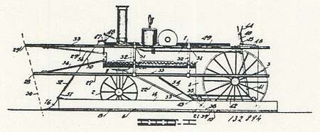
7. The combination with a traction engine provided rearwardly with traction wheels and forwardly with carriage wheels swiveled by a king bolt, of knives located to the sides of the traction engine and converging forwardly to the front of the same, said knives being narrower at the front than at the rear, plates secured to the knives and extending beyond the inner edges of the same, vertically directed shields secured to the plates permanently and being connected forwardly, cross rods passing between the shields and connected swingably at their ends to the plates, adjusting screws carried by the rods and bearing on the plates, a coulter fastened to the forward ends of the shields, a drawbar looped centrally around the king bolt aforesaid and having its ends diverging rearwardlv and secured adjustably to the plates, braces passing between the shields and the traction engine and means for raising the plates and dependencies, said means being carried by the traction engine and being operated from the same, as and for the purpose specified.
8. The combination with a traction engine, of a set of knives located to the side of the traction engine and converging forwardly to the front of the same, horizontally disposed plates secured to the knives, shields secured to the plates and being connected forwardly, slotted plates secured rearwardly to the traction engine, hangers fastened permanently to the horizontally disposed plates and provided at their upper ands with pins entering the slots, a lever located on the engine, a link fastened swingably to one of the pins, a rod passing between the lower end of the lever and the upper end of the link, a bell crank located at the front of the engine, a link connecting the
bell crank with the lever, and means connecting the bell crank with the coulter, as and for the specified.
9. The combination with a suitable supporting means, and cutting knives located to the sides of the supporting means and converging forwardly, of guard rails located to the sides of the supporting means and converging forwardly, the forward ends of the guard rails being located in advance of the converging ends of the knives, as and for the purpose specified.
10. The combination with a suitable supporting means and cutting knives located to the sides of the supporting means and converging forwardly, of a lower set of forwardly converning guard rails located to the side of the supporting means and carried by the same and having their converging ends in advance of tile forward ends of the knives, and an upper set of forwardly converging guard rails located to the sides of the supporting means and carried thereby, such latter set having their connecting ends in advance to the converging ends of the lower set. as and for the purpose specified.
11. The combination with a suitable supporting means, of an upper and lower set of gaud rails located to the sides of the supporting means and converging forwardly to the front of the same, and gatherers fixed on the guard rail., at suitable intervals, as and for the purpose specified.
12. The combination with a suitable supporting means of an upper and lower set of guard rails located to the sides of the supporting means and converging forwardly to the front d the same, and hooked gatherers permanently secured to the guard rails at suitable intervals, as and for the purpose specified.
|